1. Refrigeration and Air Conditioning Heat Exchangers
Fin-tube heat exchangers can be classified into round-based tubes, elliptical-based tubes, and flat-based tubes, among others. Fin-tube heat exchangers were developed by modifying smooth tubes, adding fins to the smooth tubes to increase the heat transfer area, and enhancing fluid turbulence to improve heat transfer efficiency. There are numerous factors influencing the heat transfer capacity of finned tube heat exchangers. This paper will introduce and analyze the development history and current status of finned tube heat exchangers both domestically and internationally. It will conduct a detailed analysis of their development process from three aspects: the materials, manufacturing processes, and structural design of the tube fins, with the aim of exploring energy-efficient finned tube heat exchangers.
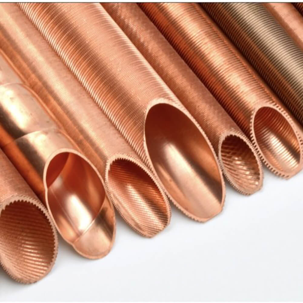
Fin tubes operate under high-temperature and high-pressure conditions, requiring the materials to possess properties such as oxidation resistance and corrosion resistance. Commonly used materials for tube fins include aluminum, aluminum alloys, copper, brass, nickel, and stainless steel.
Recent research conclusions on heat exchanger materials are as follows: (1) Aluminum fins have a certain degree of reliability, such as aluminum flat tube heat exchangers and copper-aluminum composite tube heat exchangers in air conditioning systems. (2) Aluminum heat exchangers face significant challenges in HVAC applications, primarily due to aluminum’s susceptibility to corrosion and leakage, as well as the formation of corrosion byproducts that can create fouling and thermal resistance, thereby reducing heat exchanger efficiency. This poses significant technical challenges in replacing copper with aluminum materials. (3) Copper materials have the best heat transfer performance but are the most expensive; aluminum materials have the second-best heat transfer performance and are the least expensive, but they lack corrosion resistance; stainless steel materials have the worst heat transfer performance, are moderately priced, and possess corrosion resistance.
Current situation: Many companies still use copper heat exchangers to avoid refrigerant leaks. The new trend is to use copper as the tube material and aluminum as the fins, or to use stainless steel tubes with additional outer fins to enhance heat transfer.
2. The impact of fin tube manufacturing processes on heat exchanger performance
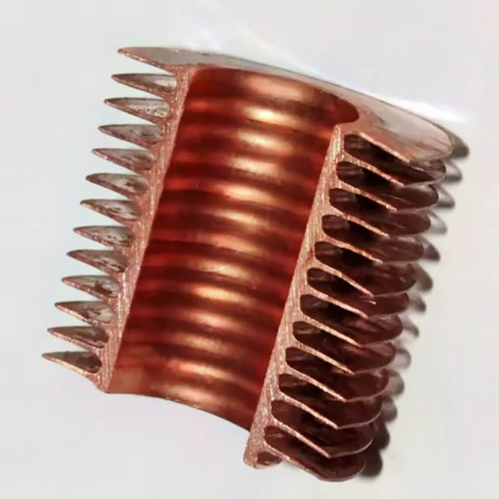
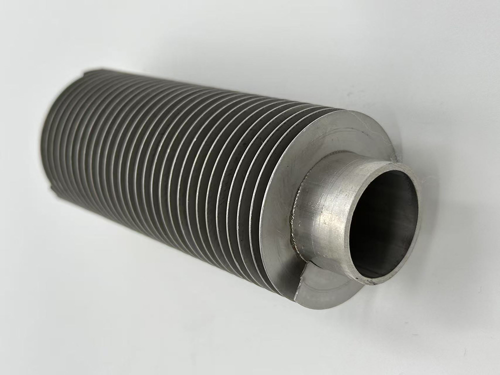
Mechanical connection refers to securing fins to the base tube surface using mechanical methods such as sleeves, inserts, or wrapping; welding refers to combining pre-designed fins with the base tube via welding, primarily including brazed spiral fin tubes and high-frequency welded spiral fin tubes.
Summary: Fin tubes are typically connected using welding for strength, but welded fin tubes are non-removable and lack the flexibility of mechanical connection methods; mechanical connection methods can introduce contact thermal resistance at the connection points, thereby affecting the heat transfer performance of the heat exchanger.
The influence of fin tube structure on heat exchanger performance:The structure of finned tubes includes the number of tube rows, fin type, and fin spacing. The following sections will discuss their impact on heat exchanger performance from these three aspects.
3. Number of Tube Rows
The number of tube rows in a finned tube heat exchanger should not be too many or too few. Too many rows can result in insufficient heat transfer area, affecting heat exchanger performance; too few rows can increase thermal resistance, reducing heat transfer efficiency.
Summary of the impact of the number of tube rows on heat transfer performance: When the finned tube has two rows, the heat transfer performance of the finned tube heat exchanger is optimal. As the number of tube rows increases, both the heat transfer coefficient and the heat transfer temperature difference decrease, but the total heat transfer first increases and then decreases. The average heat transfer per tube row also first increases and then decreases. Therefore, increasing the number of tube rows to achieve high heat transfer is an uneconomical approach.
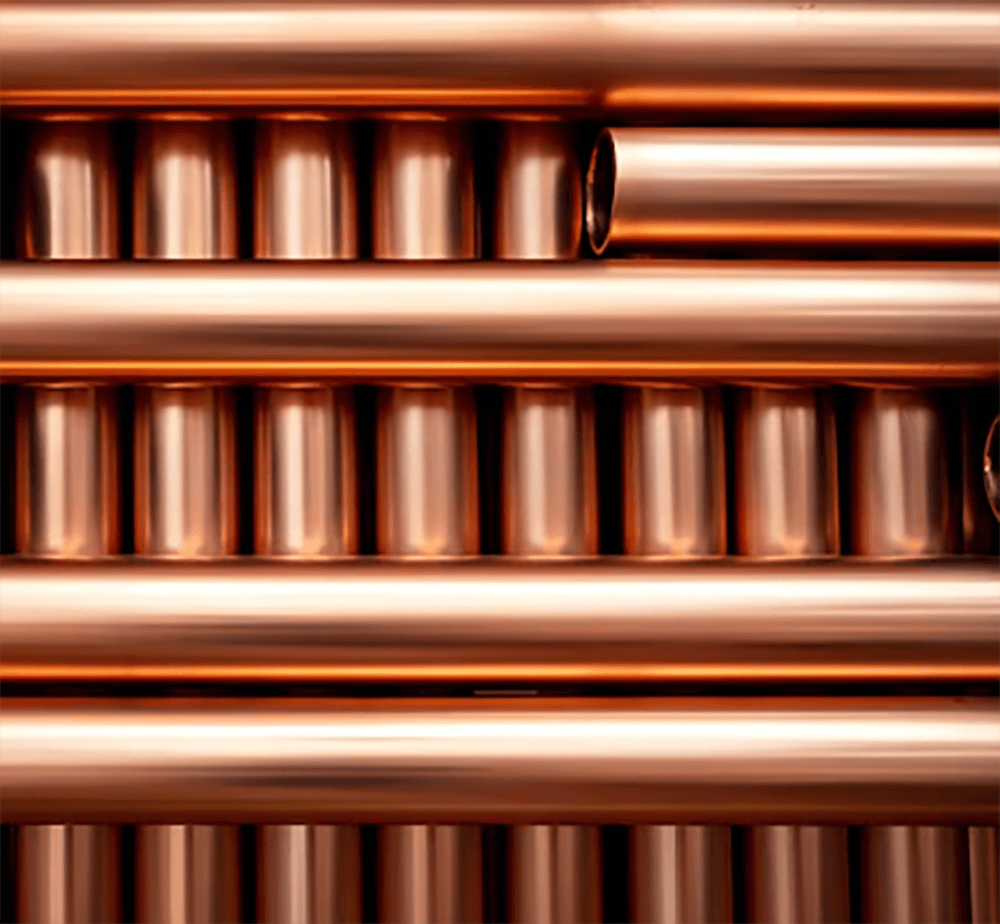
3.1 Fin Types Fin types also affect the heat transfer capacity of heat exchangers. Common fin types include flat fins, louvered fins, corrugated fins, perforated fins, and serrated fins.
3.2 Fin Spacing Fin spacing is originally designed to increase the heat transfer area. As the fin spacing increases, the airflow area increases, and the airflow resistance decreases. However, as the fin spacing continues to increase, the heat transfer area gradually decreases, leading to a reduction in heat transfer capacity.
Summary: When the fin spacing is between 4 mm and 6 mm, the size of the fin spacing has no effect on the heat transfer performance of the finned tube; the smaller the fin spacing, the faster the fin frosting rate. As the fin spacing decreases, the heat transfer rate increases, but the rate of increase in heat transfer decreases.