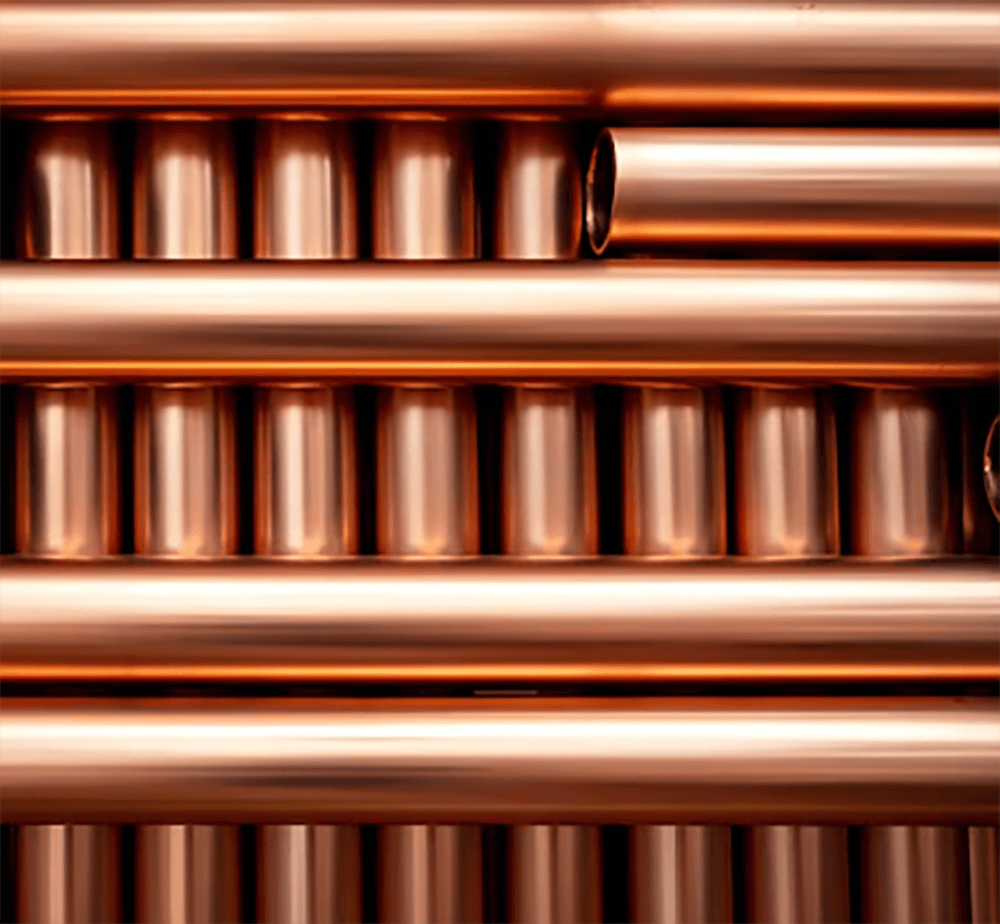
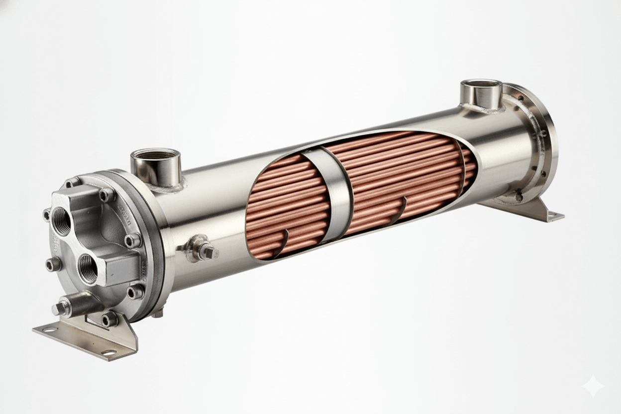
Fin tubes are the unsung heroes of heat exchange, crucial components that dramatically boost the efficiency of thermal systems by maximizing surface area. Modern engineering demands ever-greater performance from these components, pushing the boundaries of material science and design. The selection of advanced materials is no longer just about thermal conductivity; it encompasses a complex interplay of environmental resilience, manufacturability, and long-term cost-effectiveness. This article delves into the critical role of advanced materials in modern fin tube design, exploring their performance characteristics, selection criteria, and the cutting-edge applications that drive their evolution.
Cleaning Technologies for Fouled Fin Tubes: Comparing Methods for Maximum Efficiency Recovery
Fouling—the accumulation of undesirable deposits on heat transfer surfaces—is a persistent challenge for fin tubes, severely degrading their efficiency and increasing energy consumption. Effective cleaning technologies are vital for maximum efficiency recovery and prolonging service life.
Common fouling types include soot, ash, scale (from water impurities), biological growth, and process fluid residues. Choosing the right cleaning method depends on the type of foulant, the fin tube material, and accessibility.
- Mechanical Cleaning:
- Soot Blowing: Utilizes steam, air, or water jets to dislodge ash and soot in boilers and furnaces. Highly effective for dry, powdery deposits.
- Brushing/Scraping: For internal tube fouling (e.g., scale), brushes or scrapers are mechanically driven through the tubes. This is common for water-side fouling.
- High-Pressure Water Jetting (Hydro-blasting): Powerful water jets remove tough scale, hardened deposits, and biological growth from both internal and external surfaces. Can be very effective but requires careful pressure control to avoid fin damage.
- Chemical Cleaning (Chemical Flushing):
- Method: Circulating chemical solutions (acids, alkalis, chelating agents, dispersants) through the fin tubes to dissolve or loosen deposits.
- Pros: Can effectively remove stubborn scale and complex chemical foulants without mechanical abrasion.
- Cons: Requires careful selection of chemicals to avoid corrosion of the fin tube material. Disposal of spent chemicals can be an environmental concern.
- Thermal Shock:
- Method: Rapid heating or cooling of the fin tube surface to create thermal stress that dislodges brittle deposits. Common in power plants using sudden steam or air blasts.
- Pros: Effective for certain types of ash and slag.
- Cons: Can induce stress on the fin tube material, potentially leading to fatigue or cracking if not carefully controlled.
- Online Cleaning Systems:
- Acoustic Cleaners: Use high-frequency sound waves to vibrate and dislodge particulate matter from fin surfaces, preventing buildup.
- Fluidized Bed Cleaning: For some applications, passing a fluid containing abrasive particles over the fins can continuously scrub away deposits.
The ideal cleaning strategy often involves a combination of methods, preventative measures (e.g., filtration, water treatment), and regular monitoring to maintain optimal fin tube performance.
Thermal Simulation Tools for Fin Tube Applications: A Comparative Analysis for Engineers
Thermal simulation tools are indispensable for modern fin tube design, allowing engineers to predict performance, optimize configurations, and troubleshoot issues without costly physical prototypes. These tools leverage computational fluid dynamics (CFD) and finite element analysis (FEA).
- Computational Fluid Dynamics (CFD):
- Function: Simulates fluid flow (gases or liquids) and heat transfer around and within the fin tubes. It can model complex phenomena like turbulence, convection, and even phase changes.
- Software Examples: ANSYS Fluent, OpenFOAM, COMSOL Multiphysics.
- Pros: Provides detailed insights into temperature and velocity distributions, pressure drop, and local heat transfer coefficients. Excellent for optimizing fin geometry (height, thickness, spacing, shape) and tube layouts.
- Cons: Computationally intensive, requiring significant computing power and expertise to set up and interpret models.
- Finite Element Analysis (FEA):
- Function: Primarily used for structural and thermal stress analysis. It discretizes the fin tube into small elements to analyze temperature distribution, thermal expansion, and mechanical stresses under various loads.
- Software Examples: ANSYS Mechanical, Abaqus, SolidWorks Simulation.
- Pros: Crucial for predicting thermal stress, preventing fatigue failure, and optimizing material thickness. Can analyze solid conduction within the fins and tubes.
- Cons: Less suitable for detailed fluid flow analysis than CFD.
- Specialized Heat Exchanger Design Software:
- Function: Often built on empirical correlations and simplified models, these tools offer rapid preliminary design and sizing of fin tube heat exchangers. They integrate databases for material properties and fluid characteristics.
- Software Examples: HTRI Xchanger Suite, Aspen Exchanger Design and Rating.
- Pros: Fast, user-friendly for initial design iterations, and widely used in the industry for standard applications.
- Cons: Less accurate for highly complex geometries or extreme non-ideal flow conditions compared to CFD.
Comparative Analysis for Engineers:
Engineers typically employ a multi-faceted approach. Specialized design software is used for initial sizing and feasibility studies. CFD is then applied to refine critical components, optimize fluid-side performance, and address specific flow issues. FEA is utilized to verify structural integrity under thermal and mechanical loads. This integrated approach ensures both thermal efficiency and mechanical robustness, leading to optimized fin tube designs.
Fin Tubes in Green Energy: Applications in Solar Thermal and Geothermal Power Generation
Fin tubes are pivotal components in various green energy applications, enhancing the efficiency of systems designed to harness renewable resources like solar and geothermal energy.
- Solar Thermal Power Generation (Concentrated Solar Power – CSP):
- Application: In CSP plants (e.g., parabolic trough, solar tower), sunlight is concentrated onto receiver tubes to heat a working fluid (e.g., synthetic oil, molten salt, or direct steam). Fin tubes, particularly in the heat recovery steam generator (HRSG) or economizer sections, play a crucial role.
- Role of Fin Tubes: After the primary heat absorption in the solar field, the high-temperature working fluid flows to an HRSG. Here, fin tubes are extensively used to transfer heat from this hot fluid to water, generating steam. The finned design is essential because:
- Enhanced Heat Transfer: Efficiently captures residual heat from the working fluid to maximize steam production, which then drives a turbine for electricity generation.
- Compactness: Optimizes the size of the HRSG, fitting within the plant’s footprint.
- Specific Examples: Fin tubes might be found in the economizer, evaporator, and superheater sections of the HRSG, where different sections require specific fin geometries and materials to optimize heat transfer at varying temperature ranges.
- Geothermal Power Generation:
- Application: Geothermal power plants utilize heat from the Earth’s interior. In Binary Cycle Geothermal Plants, geothermal fluid (hot brine or steam) heats a secondary working fluid (e.g., isopentane, n-butane) with a lower boiling point, which then expands to drive a turbine.
- Role of Fin Tubes:
- Preheaters/Vaporizers (Evaporators): Fin tubes are critical in the heat exchangers where the geothermal fluid transfers its heat to the organic working fluid, causing it to vaporize. The finned design ensures efficient heat extraction from the geothermal fluid, maximizing the output of the organic vapor.
- Condensers: After the organic fluid expands through the turbine, it needs to be condensed back into a liquid. Fin tubes (often in air-cooled condensers) are used to efficiently reject heat to the ambient air, completing the cycle.
- Advantages:
- High Efficiency: Maximizes the heat transfer from the relatively low-temperature geothermal fluid, crucial for the efficiency of the binary cycle.
- Corrosion Resistance: Depending on the geothermal fluid’s composition (which can be highly corrosive due to minerals and dissolved gases), fin tubes are often made from specialized alloys (e.g., titanium, high-grade stainless steels) to ensure longevity.
In both solar thermal and geothermal applications, fin tubes are indispensable for efficiently converting thermal energy into usable power, underscoring their vital contribution to the global green energy transition.
Performance Restoration: Remediation Strategies for Underperforming Fin Tube Heat Exchangers
When fin tube heat exchangers start underperforming, it often signals fouling, damage, or degradation. Remediation strategies are crucial to restore performance and extend their operational life.
Common Causes of Underperformance:
- Fouling: The most frequent cause, leading to increased thermal resistance and pressure drop.
- Corrosion: Material degradation, leading to wall thinning, pitting, or tube leaks.
- Erosion: Abrasive wear, particularly in high-velocity particulate-laden flows.
- Mechanical Damage: Fin damage (bent, crushed, missing fins), tube vibration, or support failure.
- Scaling: Hard mineral deposits from water.
Remediation Strategies:
- Cleaning (Primary Strategy):
- External Cleaning:
- Soot Blowing: For powdery ash and soot (boilers).
- High-Pressure Water Jetting: For stubborn external deposits (e.g., slag, hardened ash, external scale). Requires careful control to avoid fin damage.
- Dry Ice Blasting: Non-abrasive, effective for some types of deposits, leaves no secondary waste.
- Internal Cleaning:
- Mechanical Brushing/Scraping: For internal tube scale.
- Chemical Cleaning/Flushing: For dissolving internal scale or sludge.
- Pigging: For larger diameter tubes, using specialized “pigs” to scrape internal deposits.
- External Cleaning:
- Repair and Replacement:
- Fin Repair/Reforming: For localized bent or crushed fins, manual or specialized tools can be used to re-form them, restoring some surface area and airflow.
- Tube Plugging: For leaking tubes, the most common immediate fix is to plug both ends, isolating the leak. This reduces active heat transfer area, so it’s a temporary solution or for minor leaks in large bundles.
- Tube Replacement: For widespread tube damage or when plugging too many tubes impacts performance, individual tube replacement (if feasible and economical) or replacing the entire tube bundle is necessary.
- Weld Repair: For localized corrosion or cracks in welded fin tubes, if material allows.
- Corrosion Mitigation (Post-Incident):
- Surface Coating Application: Applying specialized corrosion-resistant coatings after cleaning, if the remaining wall thickness allows.
- Water Treatment Optimization: Adjusting water chemistry (pH, inhibitors) to prevent further internal scaling or corrosion.
- Operational Adjustments:
- Temperature Control: Adjusting inlet temperatures or flow rates to avoid acid dew point corrosion.
- Flow Pattern Optimization: Adjusting gas flow distribution to mitigate erosion or uneven fouling.
- Regular Monitoring: Implementing real-time monitoring (e.g., temperature profiles, pressure drop) to detect performance degradation early.
Decision-Making Factors:
- Extent of Damage/Fouling: Minor fouling can be cleaned; severe damage may require replacement.
- Cost-Effectiveness: Comparing the cost of remediation to the cost of replacement and the value of restored performance.
- Downtime Implications: How long can the system be offline for repairs?
- Safety Considerations: Ensuring repairs are safe and adhere to standards.
By proactively diagnosing underperformance and applying appropriate remediation strategies, operators can extend the useful life of fin tube heat exchangers, optimize energy efficiency, and avoid costly full replacements.