What affects the spacing and height of finned tube heat exchangers?
The spacing and height of finned tube heat exchangers mainly affect the fin ratio, which is closely related to the membrane heat transfer coefficient of the medium inside and outside the tube. If there is a significant difference in the heat transfer coefficient between the inner and outer membranes of the tube, a finned tube with a relatively high fin ratio should be selected, such as steam heated air.
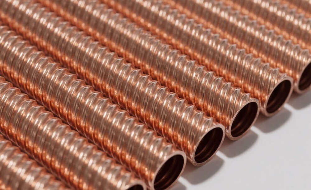
When there is a phase change in the medium on one side, the difference in heat transfer coefficient will be significant, such as in the exchange of hot and cold air. When the hot air drops below the dew point, a finned tube heat exchanger can be used. In the case of heat exchange between air without phase change, or between water and water, bare tubes are usually more suitable. Of course, low finned tubes can also be used, as this is a weak heat transfer coefficient, and strengthening either side has a certain effect. However, excessive wing ratio does not have a significant effect. The perfect situation is that the contact area between the inside and outside of the tube is strengthened simultaneously, and threaded or grooved tubes can be used.
What factors need to be considered for the spacing between fins?
The spacing between fins is mainly considered for factors such as dust accumulation, dust deposition, and ease of cleaning, while strictly meeting the equipment’s requirements for pressure drop.
When arranging, the spacing between pipes should not be too large, generally more than 1mm is suitable for laying pipes. During the heat exchange process, air mainly participates in heat transfer on the front and back surfaces of the fins when passing through the finned tube heat exchanger.
There is only a small amount of radiative heat transfer in the middle of the two finned tubes, and the heat transfer effect is not significant. Due to the absence of fins and resistance, this area is easily penetrated by air.
During the process of air heating, the cold air without heat exchange will neutralize the heated air passing through the middle of the fins, which actually reduces the heat transfer effect. Compared with foreign finned tube heat exchangers, the tube spacing is only 0.5mm larger than the outer diameter of the fins, indicating the importance of tube spacing when arranging finned tubes.
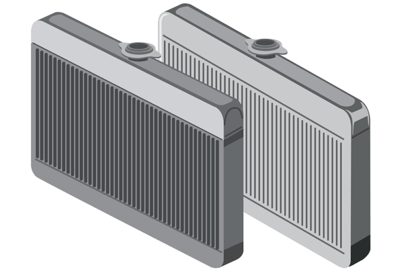
Understanding the Terms
- Tube Spacing (or Tube Pitch): This refers to the distance between the centers of adjacent tubes in the heat exchanger. It can be measured both horizontally and vertically.
- Sheet Spacing (or Fin Pitch): This refers to the distance between the centers of adjacent fins on the same tube. It determines the fin density.
Factors Affecting Spacing
Several factors influence the optimal tube and sheet spacing:
- Heat Transfer Requirements: The primary goal is to maximize heat transfer. Closer spacing generally increases heat transfer, but it also increases pressure drop.
- Pressure Drop Limitations: High pressure drop can lead to increased pumping power and operating costs. The spacing must be optimized to balance heat transfer with acceptable pressure drop.
- Fluid Properties: The properties of the fluids involved (e.g., viscosity, density, thermal conductivity) influence heat transfer and pressure drop.
- Fin Geometry: The fin height, thickness, and shape also affect the optimal spacing.
- Fouling Considerations: If there’s a risk of fouling (accumulation of deposits), wider spacing may be necessary to allow for cleaning and maintenance.
- Manufacturing Constraints: The chosen spacing must be feasible to manufacture within acceptable tolerances.
- Cost: Closer spacing generally increases the cost of the heat exchanger.
General Guidelines
While the optimal spacing depends on the specific application, here are some general guidelines:
- Tube Spacing:
- A common starting point is to have a tube pitch (center-to-center distance) that is 1.25 to 1.5 times the tube outer diameter.
- Closer spacing generally leads to higher heat transfer but also increased pressure drop.
- The tube layout (triangular, square, rotated square) also affects heat transfer and pressure drop.
- Sheet Spacing:
- The fin pitch (distance between fins) is typically chosen to balance heat transfer and pressure drop.
- Closer spacing increases heat transfer but also increases pressure drop and the risk of fouling.
- The optimal fin pitch depends on the fin height and the specific application.
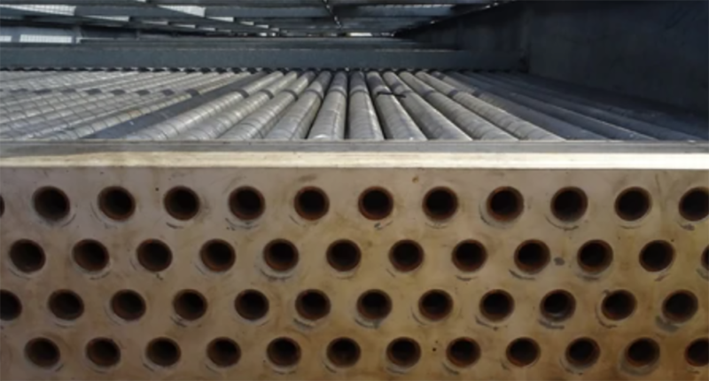
Optimization Process
Determining the optimal tube and sheet spacing often involves an iterative process:
- Initial Design: Start with an initial design based on general guidelines and experience.
- Thermal and Hydraulic Calculations: Perform calculations to estimate the heat transfer performance and pressure drop for the chosen spacing.
- CFD Analysis (Optional): Computational Fluid Dynamics (CFD) can be used for more detailed analysis and optimization of the flow and heat transfer within the heat exchanger.
- Iterative Refinement: Adjust the spacing based on the calculations and analysis to achieve the desired performance while meeting pressure drop and other constraints.
Tools and Resources
- Heat Exchanger Design Software: Specialized software tools can assist in the design and optimization of finned tube heat exchangers.
- CFD Software: CFD software packages can be used for detailed flow and heat transfer analysis.
- Manufacturer’s Data: Consult with finned tube manufacturers for their recommendations and technical data on specific fin geometries and performance characteristics.
Important Considerations
- Standards and Codes: Adhere to relevant industry standards and codes for heat exchanger design and safety.
- Experience and Expertise: It’s often beneficial to consult with experienced heat exchanger designers or engineers to ensure optimal design and performance.
In summary, while closer fin spacing can enhance heat transfer efficiency by increasing surface area, it must be balanced against potential drawbacks such as airflow obstruction and maintenance challenges. Careful design consideration is essential to optimize fin spacing for specific applications to achieve the best overall efficiency in finned tube heat exchangers. For instance, applications requiring rapid heat exchange may benefit from tighter spacing, while those prioritizing low pressure drops might favor wider spacing. Setting appropriate tube and sheet spacing in finned tube heat exchangers involves careful consideration of various parameters including thermal performance, pressure drop, maintenance needs, and fluid characteristics. Balancing these factors will ensure optimal operation of the heat exchanger while maintaining efficiency and reliability in its application.

