In the world of thermal engineering, the quest for efficiency is relentless. Heat exchangers are fundamental components in a vast array of industrial processes, and their performance is often the single most critical factor determining a system’s overall effectiveness. At the heart of many of these devices lies the finned tube, an ingenious solution for enhancing heat transfer between a fluid flowing inside a tube and another fluid (often a gas like air) flowing outside. By strategically adding fins to the exterior of the tube, the surface area available for heat exchange is dramatically increased. However, the true benefit of this design depends on a thorough understanding of fin efficiency—the measure of how effectively the fin transfers heat from its base to its tip. A holistic approach that considers material science, geometry, manufacturing, and maintenance is essential for maximizing a heat exchanger’s output.
The Science Behind Finned Tube Heat Exchangers: Principles, Parameters and Performance
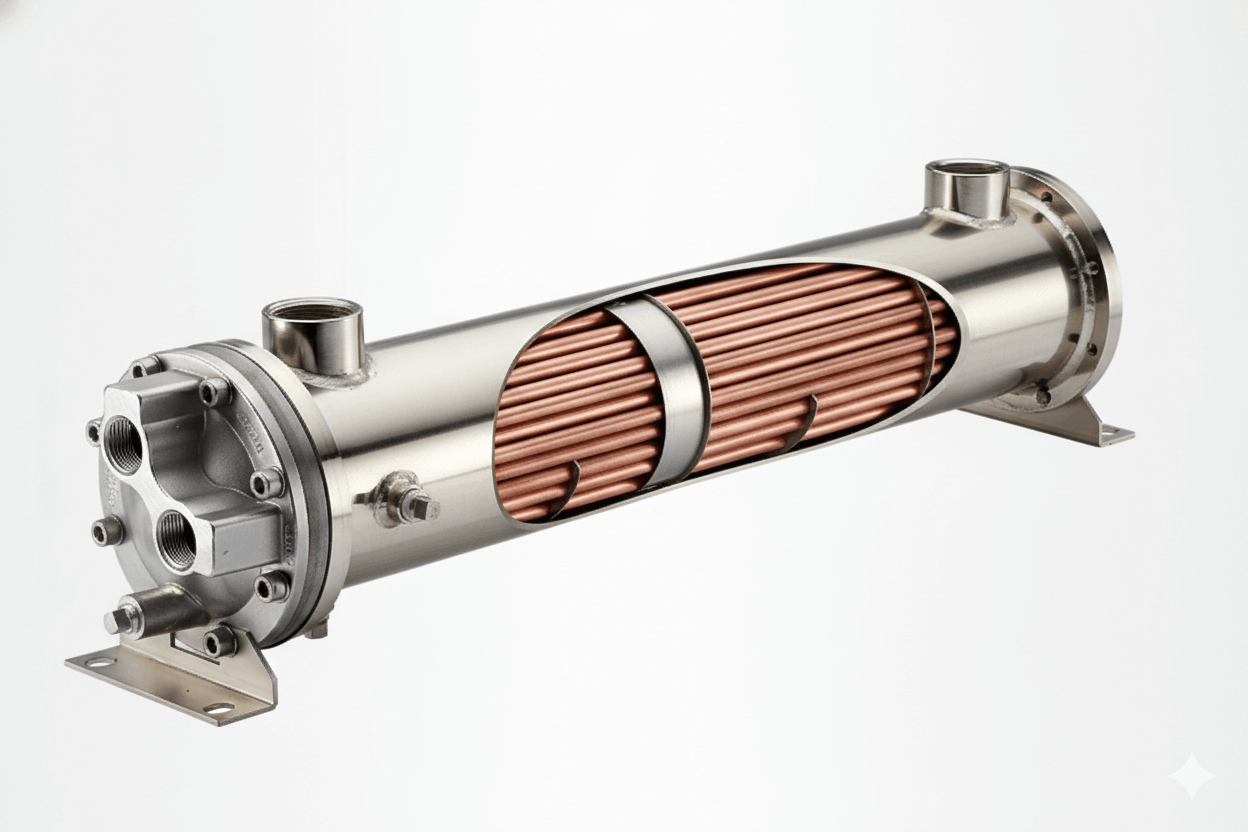
A finned tube heat exchanger operates on the principle of extending the primary heat transfer surface. The central challenge in gas-to-liquid heat exchange is that gases have a much lower heat transfer coefficient than liquids. By adding fins to the gas side, the surface area is significantly expanded, effectively “forcing” the gas to interact with more of the heated surface. The performance of the exchanger is governed by key parameters. Thermal conductivity of the fin material dictates how quickly heat moves from the tube to the tip of the fin. The heat transfer coefficient for the gas and the liquid, along with the log mean temperature difference (LMTD), determine the overall rate of heat exchange. Finally, fin efficiency, which is the ratio of actual heat transferred by the fin to the heat that would be transferred if the entire fin were at its base temperature, is the ultimate metric for a fin’s effectiveness.
The total heat transfer area of a finned tube heat exchanger is not simply the sum of the tube area and the fin area. Because of the temperature drop along the fin, the outer surface is not as effective as the inner tube surface. To accurately quantify the heat exchange capacity, one must calculate the effective heat transfer area. This calculation involves the primary tube surface area plus the product of the finned surface area and the fin efficiency. This is a critical step in the design process, ensuring that the theoretical performance matches the real-world output. The formula for overall heat transfer () is given by , where is the overall heat transfer coefficient and is the effective heat transfer area. This formula underscores why a proper calculation is essential for any design.
Transverse vs. Longitudinal Fins: Choosing the Right Configuration for Your Industry Application
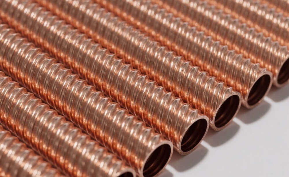
The geometry of a fin is determined by the application. The two most common configurations are transverse fins and longitudinal fins. Transverse fins are mounted perpendicularly to the tube’s axis, either as individual plates or as a continuous spiral strip. This design is highly effective for cross-flow applications, where the external fluid flows at a right angle to the tubes. They are prevalent in air conditioners, radiators, and dry coolers due to their ability to maximize contact with the airflow.
In contrast, longitudinal fins run parallel to the tube’s axis. These are often used when the external fluid flows in a parallel direction to the tube, such as in double-pipe heat exchangers or applications where the external fluid has a relatively low flow velocity. The choice between transverse and longitudinal fins is dictated by the fluid dynamics of the system, with each configuration offering distinct advantages for specific industry applications.
Beyond the overall configuration, the detailed fin geometry and spacing are critical to performance. Fin spacing, or the number of fins per unit length, is a trade-off. A higher fin density increases the total heat transfer area but also leads to a higher air-side pressure drop, which requires more fan power and increases energy consumption. It can also create a greater risk of fouling as particulate matter gets trapped between the fins. Fin thickness is another key factor. A thicker fin will have a higher thermal conductivity, but it will also add more weight and cost to the unit. The optimal design balances these variables to achieve the best heat transfer rate for the given energy input.
Air-Side Heat Transfer Enhancement: Advanced Fin Designs for Industrial Applications
For many industrial applications, simply adding fins is not enough. Air-side heat transfer enhancement is achieved through advanced fin designs that create turbulence in the airflow, disrupting the boundary layer and increasing the heat transfer coefficient. Corrugated fins, with their wavy surface, and louvered fins, which have small cuts that redirect airflow, are two such examples. These designs break up the laminar flow of the air, ensuring that a larger portion of the fin surface is actively engaged in heat exchange. While they can increase the air-side pressure drop, the gains in heat transfer often justify the higher fan power.
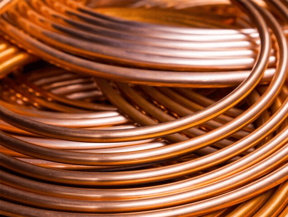
The material selection for both the tube and fins is a foundational decision in the design process. The tube is often made of copper, steel, or stainless steel, while the fins are typically aluminum or copper. Thermal conductivity is the primary consideration for the fins, as it determines how efficiently heat is conducted from the base to the fin tip. Aluminum has a high thermal conductivity, is lightweight, and is relatively inexpensive, making it a popular choice. Copper has even higher thermal conductivity and excellent corrosion resistance, but at a greater cost. The durability of the material is also crucial, especially in corrosive or high-temperature environments.
Manufacturing Methods for Finned Tubes: Impact on Quality, Performance and Cost
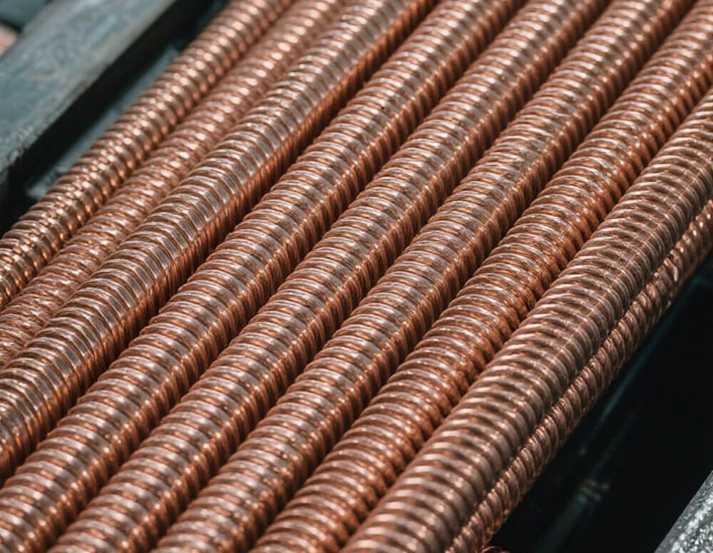
The way a finned tube is manufactured directly affects its quality, performance, and cost. Common methods include mechanical tension winding, extrusion, and brazing. In mechanical winding, a fin strip is wrapped around a tube under tension, creating a tight mechanical bond. This is a cost-effective method but can have lower thermal efficiency than other methods. Extruded fins are an integral part of the tube itself, created by pushing a single metal sleeve over a core tube. This process ensures a perfect metallurgical bond, leading to superior heat transfer. Brazed fins are metallurgically bonded to the tube, offering excellent thermal performance, albeit at a higher cost.
The thermal performance comparison between a plain tube and a finned tube is dramatic. A plain tube has a very limited surface area for heat exchange, making it inefficient for gas-to-liquid applications. When fins are added, the effective surface area can increase tenfold or even more. The difference in BTU output can be monumental. Furthermore, the performance of different finned tube designs varies under different operating conditions. For example, a design optimized for low-temperature applications will differ from one designed for high-temperature exhaust gas recovery. This highlights the need for custom-engineered solutions.
Industrial Applications of Finned Tube Heat Exchangers: Case Studies Across Different Sectors
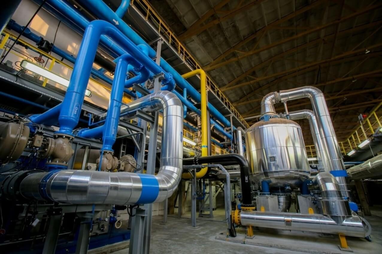
Finned tube heat exchangers are ubiquitous in industry. In the HVAC sector, they are used in air conditioners, furnaces, and chillers. In power generation, they are critical for boiler economizers and air preheaters, improving the efficiency of the boiler cycle. The chemical processing sector uses them in process fluid heating and cooling. In the petrochemical industry, they serve as air-cooled condensers. Each of these case studies illustrates how a custom-designed finned tube heat exchanger is essential for a specific set of parameters and requirements.
Despite their robust design, finned tube heat exchangers can experience issues. The most common problems include fouling, where dirt, dust, or other contaminants build up on the fin surface, restricting airflow and decreasing heat transfer. Corrosion, particularly in harsh environments, can degrade the fins and tubes, leading to a loss of performance and potential leaks. Airflow restriction due to blockages or fan failures can also severely impact efficiency. A proper troubleshooting process involves visually inspecting the fins, checking for pressure drops across the coil, and monitoring the fluid temperatures to identify any anomalies.
Maintenance Best Practices for Extended Surface Heat Exchangers in Industrial Settings
To ensure longevity and consistent performance, a comprehensive maintenance program is non-negotiable. Maintenance best practices for finned tube heat exchangers include regular visual inspections for signs of damage or fouling. Scheduled cleaning, using a mix of compressed air, water, or chemical solutions, is essential to remove built-up contaminants. It is also important to periodically check the fan motors and bearings for wear and tear. A proactive maintenance schedule can prevent costly failures and ensure the heat exchanger operates at its peak efficiency for years.
Modern engineering has moved beyond traditional calculations. Computational Fluid Dynamics (CFD) has become an indispensable tool for designing and optimizing finned tube heat exchangers. CFD analysis simulates the airflow patterns around different fin configurations, providing detailed performance insights that would be impossible to obtain through physical testing alone. Engineers can use CFD to visualize pressure drops, identify areas of low heat transfer, and fine-tune fin geometry and spacing to achieve maximum efficiency before a single prototype is built.
The Evolution of Finned Tube Technology: From Basic Designs to High-Performance Systems
The evolution of finned tube technology is a story of continuous refinement. Early designs were simple and functional, but over time, engineers have integrated advanced concepts to create high-performance systems. This evolution has been driven by the need for greater energy efficiency, the development of new materials, and a deeper understanding of fluid dynamics and heat transfer. Today’s finned tube heat exchangers are highly engineered components, a far cry from their basic predecessors.
The sum of all these factors—advanced materials, precise geometry, and meticulous maintenance—culminates in significant energy efficiency improvements. An optimized finned tube heat exchanger design minimizes the energy required to move air and liquid while maximizing the heat transfer rate. This holistic approach ensures that every component is working in synergy. By making smart design choices and committing to a robust maintenance schedule, engineers can unlock the full potential of these critical components, leading to lower operating costs and a reduced environmental footprint.