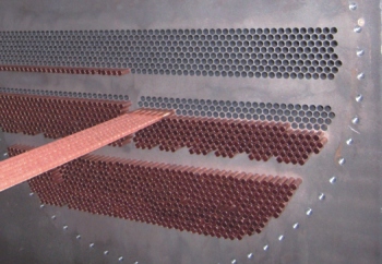
Heat exchangers are indispensable components across virtually all industrial sectors, facilitating the transfer of thermal energy between two or more fluids at different temperatures. Among the various types, finned tube heat exchangers, particularly those within the broader category of shell and tube heat exchangers, stand out for their robust design and widespread applicability. These devices are critical for optimizing energy consumption, managing process temperatures, and ensuring the efficiency and safety of industrial operations. Understanding their diverse configurations, performance characteristics, and maintenance requirements is key to making informed selection decisions.
Fixed vs. U-Tube vs. Floating Head: Which Heat Exchanger Is Right for Your Industrial Application?
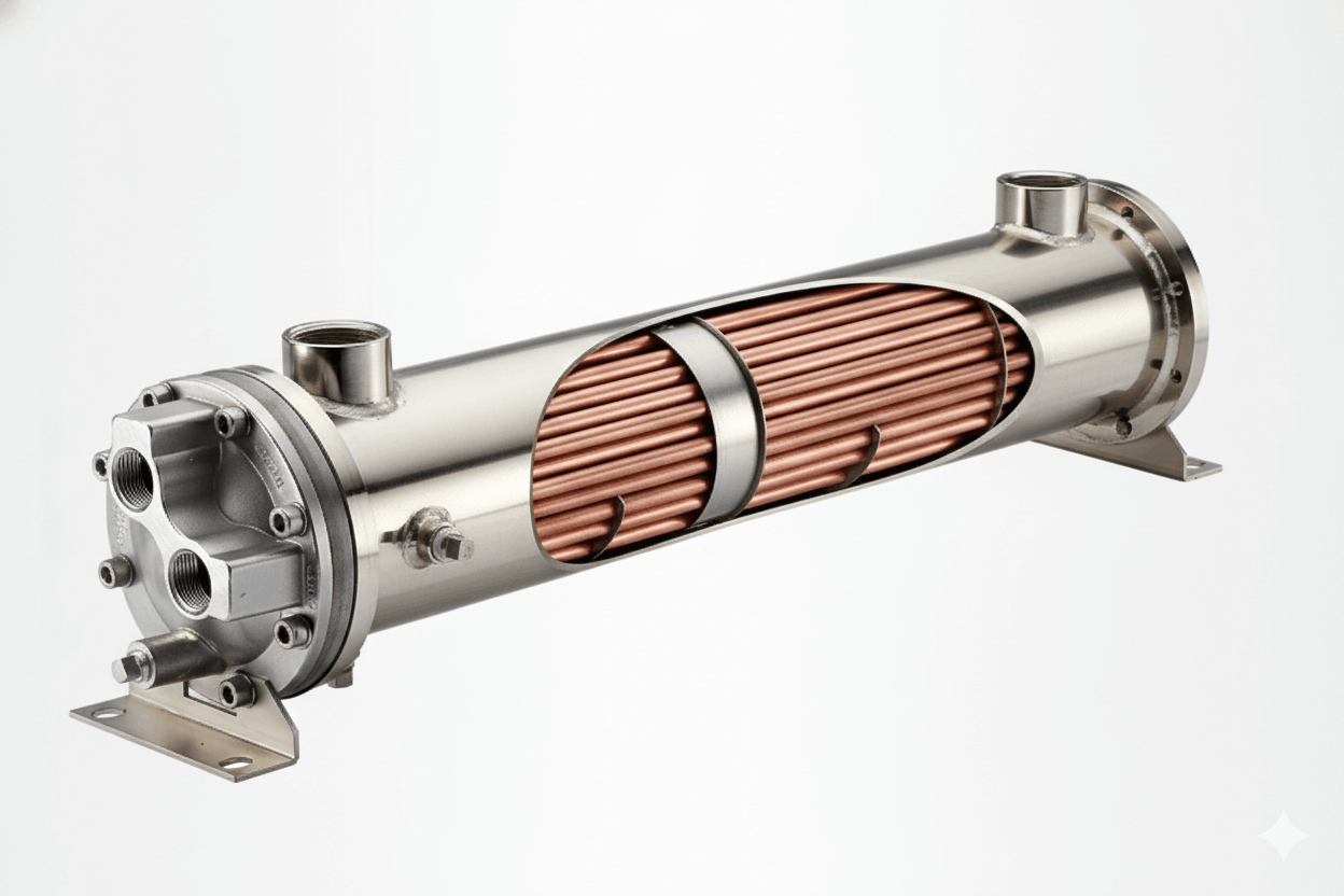
The shell and tube heat exchanger family offers several primary mechanical configurations, each with distinct advantages and disadvantages that dictate their suitability for specific industrial applications.
-
Fixed Tubesheet Heat Exchanger:
- Description: Both tubesheets are welded directly to the shell. This creates a highly rigid and robust structure.
- Advantages: Simpler and generally less expensive to manufacture. Provides a very strong and leak-tight design, making it suitable for high-pressure and high-temperature applications. Cleaning on the tube side is relatively straightforward.
- Disadvantages: Thermal stress can be a significant issue if there’s a large temperature difference between the shell fluid and the tube fluid, as the tubes and shell expand at different rates. The tube bundle cannot be removed for cleaning on the shell side, making chemical cleaning or mechanical cleaning from the outside (if accessible) the only options.
- Best For: Applications where the temperature difference between fluids is small, or where one fluid is clean and unlikely to foul the shell side (e.g., steam condensers, oil coolers with clean cooling water).
-
U-Tube Heat Exchanger:
- Description: The tubes are bent into a “U” shape, with both ends terminating in the same tubesheet. This tubesheet is then welded to the shell.
- Advantages: The U-bend design inherently accommodates thermal expansion and contraction, making it ideal for applications with large temperature differentials between shell and tube fluids. The tube bundle can be removed for cleaning and inspection of both the tube and shell sides. Simpler design with only one tubesheet reduces potential leak paths.
- Disadvantages: Cleaning the inside of the U-bend tubes can be challenging due to the bend radius. Individual tube replacement is difficult or impossible without specialized tools.
- Best For: High-temperature difference applications, processes with dirty shell-side fluids, and situations requiring easy tube bundle removal for maintenance (e.g., reboilers, condensers).
-
Floating Head Heat Exchanger:
- Description: One tubesheet is fixed to the shell, while the other (“floating head”) is free to move relative to the shell. This movement allows for differential thermal expansion.
- Advantages: Offers the most robust solution for managing large thermal stresses. Both the tube bundle and the shell side are fully accessible for mechanical cleaning, making it excellent for heavily fouling fluids on either side.
- Disadvantages: More complex to manufacture and generally the most expensive option. Requires specialized seals on the floating head, which can be potential leak points if not properly maintained.
- Best For: Applications with significant temperature differentials, highly fouling fluids on both shell and tube sides, and processes requiring frequent and thorough cleaning (e.g., chemical processing, crude oil preheaters).
The selection among these types hinges on a detailed analysis of operating temperatures, pressures, fluid characteristics (fouling potential, corrosivity), maintenance requirements, and budget constraints.
How to Select the Optimal Heat Exchanger Design for Energy-Intensive Industries: A Comprehensive Guide
Selecting the optimal heat exchanger design for energy-intensive industries, where even marginal efficiency gains translate to substantial energy savings, is a multifaceted process.
-
Process Requirements Definition:
- Heat Duty: The amount of heat to be transferred per unit of time.
- Fluid Properties: Specific heat, density, viscosity, thermal conductivity, phase (liquid, gas, two-phase), corrosivity, fouling potential for both hot and cold fluids.
- Operating Conditions: Inlet/outlet temperatures, operating pressures, and allowable pressure drops for both streams.
- Space & Weight Constraints : Physical footprint and structural support limitations.
-
Thermal Design Considerations:
- Heat Transfer Coefficients : Maximizing these is key. Factors include fluid velocities, turbulators (for enhanced turbulence), and finned tubes (to increase surface area, especially for gas-phase heat transfer).
- Log Mean Temperature Difference (LMTD) : Optimizing flow arrangements (counter-flow is generally more efficient than co-current) to maximize the driving force for heat transfer.
- Flow Arrangements: Single-pass, multi-pass, cross-flow arrangements, and the number of passes on both shell and tube sides significantly impact LMTD and pressure drop.
-
Mechanical Design Considerations:
- Material Selection : Based on fluid corrosivity, operating temperatures, and pressures (e.g., carbon steel, stainless steel, nickel alloys, titanium).
- Tube Diameter & Pitch : Affects heat transfer area, pressure drop, and cleanability.
- Baffle Type & Spacing: Influences shell-side flow patterns, heat transfer, and pressure drop. Segmental baffles are common, but more advanced designs like helical baffles offer improved flow distribution and reduced pressure drop.
- Thermal Expansion Management: As detailed above, selecting between fixed, U-tube, or floating head designs to mitigate thermal stress.
-
Maintenance & Operation Considerations:
- Fouling Mitigation: Ease of cleaning, selection of materials that resist fouling, and design for appropriate fluid velocities.
- Inspection & Repair : Accessibility for inspection, tube plugging capabilities, and ease of tube bundle removal.
By systematically evaluating these criteria, engineers can select a heat exchanger design that delivers optimal thermal performance, operational reliability, and cost-effectiveness for the energy-intensive process.

Heat Exchanger Maintenance Guide: Cleaning Methods for Different Shell and Tube Configurations
Effective maintenance, particularly cleaning, is paramount for restoring and maintaining heat exchanger efficiency, as fouling can drastically reduce performance. The cleaning method depends heavily on the heat exchanger configuration and the nature of the foulant.
-
Mechanical Cleaning :
- Hydroblasting/Water Jetting : Uses high-pressure water jets to remove soft to medium-hard deposits. Highly effective for tube-side cleaning in fixed tubesheet and floating head exchangers when tubes are accessible. Shell-side hydroblasting is possible for removable bundles (U-tube, floating head).
- Brushing/Drilling : Specialized brushes or drill bits are used to physically scrape away hard deposits from inside tubes. Requires tube access from both ends for fixed tubesheet, or one end for U-tube (though U-bends are still challenging).
- Pigging : Spherical devices (“pigs”) are pushed through tubes by fluid pressure to scrape away soft deposits.
- Applicability: Best for hard, tenacious scales, or large particulate buildup. Most effective when tube bundles are removable and accessible.
-
Chemical Cleaning :
- Circulation/Soaking : Involves circulating or soaking the heat exchanger with chemical solutions (acids, bases, chelating agents, solvents) designed to dissolve or loosen specific types of fouling (e.g., scale, bio-fouling, organic deposits).
- Clean-In-Place (CIP) : Many designs, especially fixed tubesheet, rely heavily on CIP chemical cleaning, as the shell side is inaccessible for mechanical methods.
- Applicability: Effective for softer deposits, biological films, corrosion products, and in situations where mechanical access is difficult (e.g., tight tube bundles, complex shell-side geometries, or fixed tubesheet shell sides). Requires careful selection of chemicals to avoid material degradation and proper waste disposal.
-
Combination Methods: Often, a combination of chemical and mechanical cleaning is most effective. Chemical pre-treatment can soften tough deposits, making subsequent mechanical removal easier and less abrasive.
The ease of maintenance and choice of cleaning method should be a major consideration during the initial selection of a heat exchanger type.
Cost-Benefit Analysis of Shell and Tube Heat Exchanger Types for Process Industry Applications
The choice of shell and tube heat exchanger type involves a critical cost-benefit analysis, weighing initial capital expenditure against long-term operational and maintenance costs.
-
Fixed Tubesheet:
- Initial Cost: Lowest (due to simpler construction).
- Benefits: High structural integrity, less prone to leakage, robust.
- Limitations/Costs: High thermal stress if is large (leading to potential tube buckling or tubesheet cracking), difficult shell-side cleaning (higher chemical cleaning costs, longer downtime if mechanical cleaning is needed and involves cutting/re-welding).
- Cost-Benefit: Best for applications with low fouling potential on the shell side and moderate temperature differences, where low initial cost and high structural reliability are prioritized.
-
U-Tube:
- Initial Cost: Moderate (one tubesheet).
- Benefits: Handles large thermal differences inherently, removable tube bundle for shell-side cleaning, single tubesheet reduces leak points.
- Limitations/Costs: Tube-side cleaning of U-bends can be challenging, individual tube replacement difficult, high pressure drop on tube side for certain configurations.
- Cost-Benefit: Excellent value for applications with high thermal expansion issues and a need for shell-side cleanability. Its balance of cost and flexibility makes it very popular.
-
Floating Head:
- Initial Cost: Highest (most complex construction, specialized sealing).
- Benefits: Unmatched ability to handle severe thermal differences, full access to both tube and shell sides for mechanical cleaning, ideal for highly fouling fluids.
- Limitations/Costs: Potential for leakage at floating head seals (requires vigilant maintenance), higher maintenance labor due to disassembly complexity, higher material costs.
- Cost-Benefit: Justified for the most demanding applications where fouling is severe on both sides, thermal stress is high, and frequent, thorough mechanical cleaning is essential, despite the higher upfront and maintenance costs. The extended uptime and reduced cleaning time often offset the higher initial investment.
The cost-benefit analysis should encompass the entire lifecycle of the heat exchanger, considering energy efficiency, maintenance frequency and methods, anticipated downtime, and the impact of fouling on production continuity.
High-Temperature Heat Transfer: Selecting the Right Shell and Tube Exchanger for Extreme Conditions
Transferring heat at extreme temperatures (e.g., above 400°C or 750°F) imposes significant challenges on material selection, mechanical design, and operational reliability of shell and tube heat exchangers.
- Material Selection:
- High-Temperature Alloys: Carbon steel is unsuitable. Stainless steels (300 series), nickel-based alloys (e.g., Inconel, Hastelloy), or specialized high-temperature alloys are required for tubesheets, tubes, shell, and internal components due to their improved creep resistance, oxidation resistance, and strength at elevated temperatures.
- Gaskets and Seals: Must withstand high temperatures and pressures without degradation (e.g., spiral wound gaskets with graphite filler, specific metallic gaskets).
- Thermal Expansion Management:
- Floating Head Design: Often the preferred choice for extreme temperature applications because it can freely accommodate significant differential thermal expansion between the tubes and the shell, preventing damaging stresses.
- Expansion Joints: For fixed tubesheet designs, external expansion joints on the shell side may be necessary to absorb thermal stress, but they add complexity and are potential failure points.
- U-Tube: Also a good option due to its inherent flexibility in the U-bends.
- Mechanical Strength & Pressure Containment:
- Thicker Walls: Shells and tubes may require thicker walls to maintain mechanical integrity and pressure containment at elevated temperatures where material strength is reduced.
- Flange Design: High-pressure/high-temperature flanges require robust designs and careful bolt tightening procedures.
- Fouling at High Temperatures: Fouling mechanisms can change at high temperatures (e.g., coking, polymerization). Ease of cleaning remains a crucial consideration, favoring designs with removable bundles.
- Flow Distribution: Ensuring uniform flow distribution is even more critical at high temperatures to prevent hot spots that can lead to localized overheating and material failure.
Selecting a heat exchanger for extreme conditions necessitates close collaboration with experienced manufacturers and materials specialists to ensure a safe, reliable, and efficient solution that withstands the rigors of high-temperature service.