Pressure drop is a critical parameter when designing and evaluating heat exchangers, particularly when dealing with helical finned tube banks. In industries such as HVAC, power generation, and chemical processing, understanding how to calculate the pressure drop in these systems is essential for optimizing efficiency, minimizing energy consumption, and ensuring reliable system performance. The question then arises: Is there a formula to find the pressure drop in helical finned tube banks?
Understanding the Pressure Drop in Heat Exchangers
Pressure drop refers to the reduction in pressure that occurs as a fluid flows through a system, whether it be a tube, duct, or heat exchanger. In the context of heat exchangers, pressure drop is caused by friction and turbulence as the fluid moves across the tube surfaces and through the finned sections. The primary goal in calculating pressure drop is to assess the impact it has on energy consumption and pump or fan requirements.
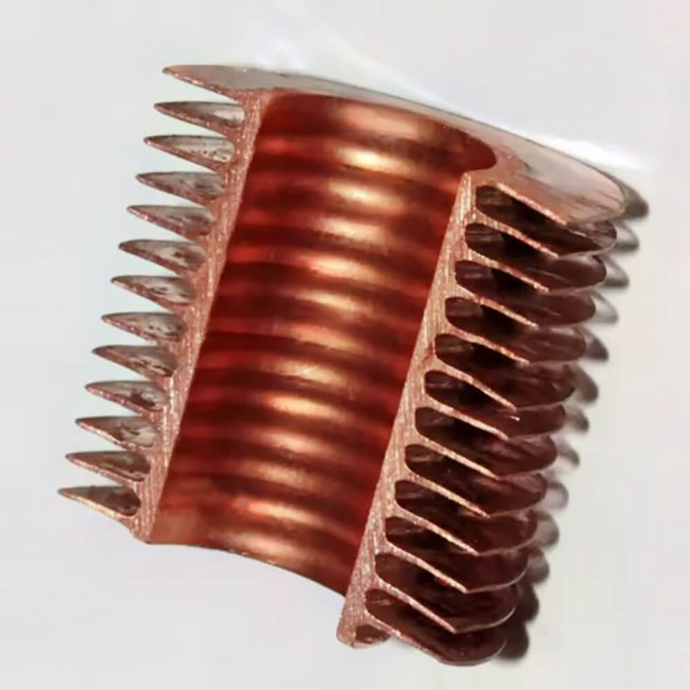
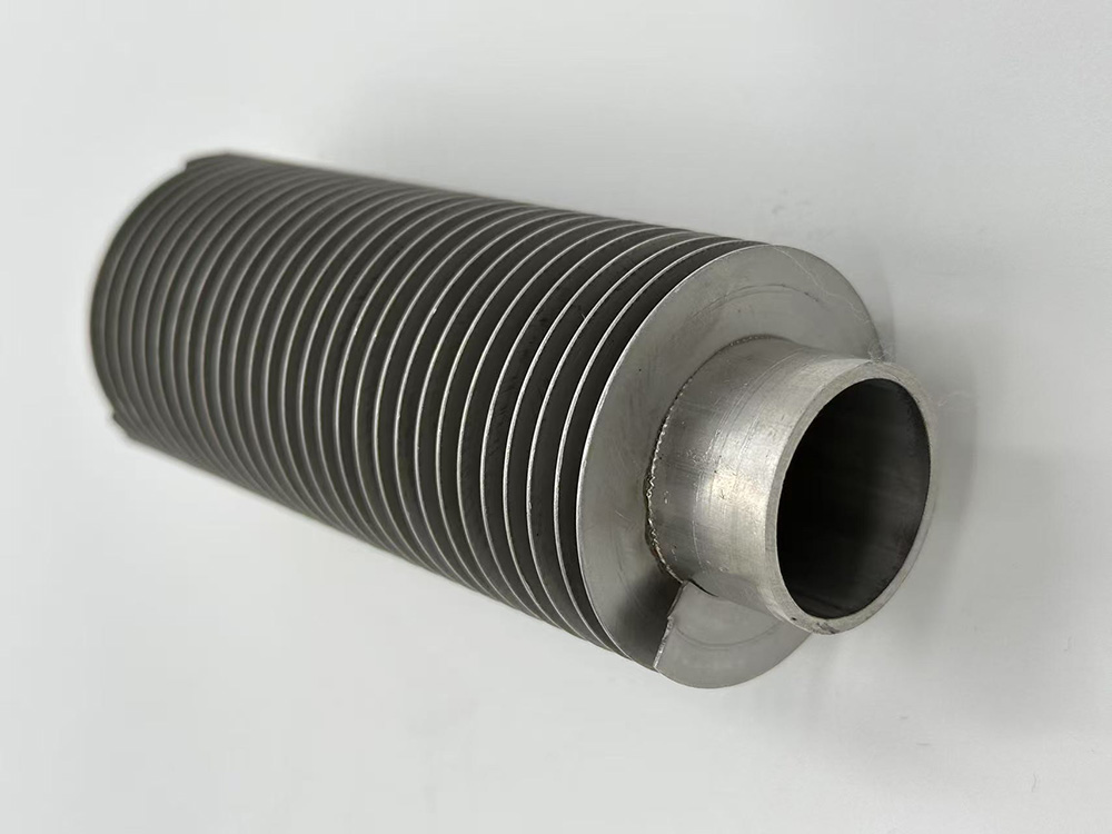
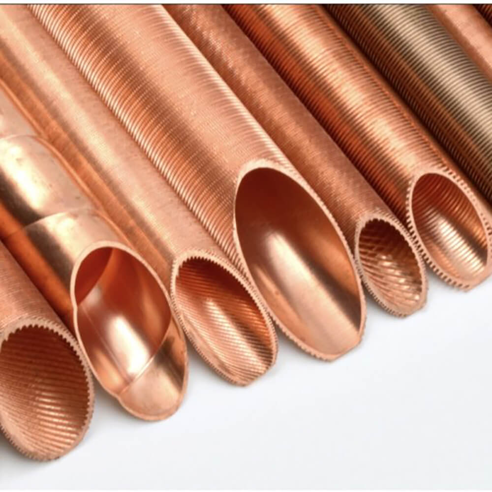
In systems with helical finned tubes, the pressure drop is influenced by several factors, including the fluid velocity, the geometry of the tube and fins, and the characteristics of the flow—whether it’s laminar or turbulent. Helical finned tubes are often used in heat exchangers because of their enhanced heat transfer properties due to the increased surface area. However, the increase in surface area comes with a cost—the additional pressure drop.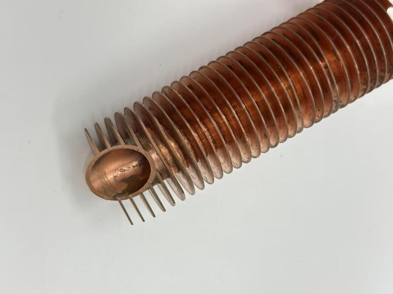
Why Is Pressure Drop Important for Helical Finned Tube Banks?
Helical finned tubes are designed to enhance heat transfer by providing a larger surface area for heat exchange. However, this design can also create more resistance to the flow of the fluid, which leads to an increase in pressure drop. Understanding and controlling the pressure drop is critical for several reasons:
- Energy Consumption: The greater the pressure drop, the more energy is required to pump or circulate the fluid through the system. This can increase operational costs and reduce the overall efficiency of the heat exchanger.
- Flow Distribution: Excessive pressure drop can lead to uneven flow distribution, resulting in poor heat transfer efficiency in some areas of the heat exchanger.
- System Reliability: If the pressure drop is too high, the system may be at risk of failure due to overpressure or excessive strain on pumps and fans.
Factors Affecting Pressure Drop in Helical Finned Tube Banks
Before diving into the formula, it’s important to understand the key factors that influence pressure drop in a helical finned tube bank:
- Fluid Velocity: The speed at which the fluid moves through the tubes has a direct impact on pressure drop. Higher fluid velocities generally result in higher pressure drops due to increased friction and turbulence.
- Tube Geometry: The diameter and length of the tubes, as well as the tightness and number of the fins, will affect how the fluid flows and how much resistance it encounters.
- Fin Geometry: The height, thickness, and pitch of the fins are crucial in determining the flow resistance. Helical fins, by their very nature, create a spiraling effect in the fluid, which can increase turbulence and therefore pressure drop.
- Fluid Properties: The type of fluid (air, water, or another medium) also influences the pressure drop calculation. The fluid’s density, viscosity, and Reynolds number play key roles in flow behavior and resistance.
- Flow Regime: The flow inside the tube can be either laminar (smooth) or turbulent (chaotic). Turbulent flow generally leads to higher pressure drops due to increased friction.
Formula for Pressure Drop in Helical Finned Tube Banks
While there is no simple one-size-fits-all formula for pressure drop in helical finned tube banks, engineers commonly rely on a modified version of the Darcy-Weisbach equation to estimate pressure drop in these types of heat exchangers. The general form of this equation is:
ΔP=f×LD×ρv22\Delta P = f \times \frac{L}{D} \times \frac{\rho v^2}{2}ΔP=f×DL×2ρv2Where:
- ΔP\Delta PΔP = Pressure drop (Pa)
- fff = Darcy friction factor (dimensionless)
- LLL = Length of the tube (m)
- DDD = Diameter of the tube (m)
- ρ\rhoρ = Density of the fluid (kg/m³)
- vvv = Fluid velocity (m/s)
However, for helical finned tubes, this basic formula needs to be adapted to account for the added complexity of the fins, the helical geometry, and the increased surface area. The equation becomes more complex, and often empirical correlations or charts specific to helical finned tubes are used in practice.
1. Friction Factor for Finned Tubes
The friction factor fff can be estimated using established empirical correlations or charts derived from experimental data for helical finned tubes. These correlations typically take into account the fin geometry, flow regime, and fluid characteristics.
In many cases, the friction factor fff is calculated using the following formula:
f=(0.079Re0.25)f = \left( \frac{0.079}{Re^{0.25}} \right)f=(Re0.250.079)Where:
- ReReRe = Reynolds number (dimensionless), which is a function of fluid velocity, tube diameter, and fluid viscosity.
For turbulent flow, the pressure drop increases due to the interaction between the fluid and the fins, which create additional resistance. The helical nature of the fins can create swirling flow patterns that increase turbulence, and thus the friction factor.
2. Equivalent Diameter for Finned Tubes
To account for the fins, the diameter DDD in the Darcy-Weisbach equation is often replaced by the equivalent hydraulic diameter of the finned tube. This equivalent diameter incorporates both the internal diameter of the tube and the external surface area created by the fins.
The equivalent diameter DeqD_{eq}Deq for a finned tube is given by:
Deq=Dtube+2×Fin Height2D_{eq} = \frac{D_{\text{tube}} + 2 \times \text{Fin Height}}{2}Deq=2Dtube+2×Fin HeightWhere:
- DtubeD_{\text{tube}}Dtube = Inner diameter of the tube
- Fin Height = The height of the fin attached to the tube.
This adjustment accounts for the increased surface area and the added resistance to flow caused by the fins.
3. Additional Considerations
In practical applications, engineers often rely on computational fluid dynamics (CFD) simulations or experimentally derived charts to calculate the pressure drop more accurately. These methods take into account the complex interaction between the fluid, the fins, and the helical geometry. They are particularly useful for systems with more intricate designs or for flows that deviate significantly from the ideal conditions assumed by the basic formulas.
Conclusion: Simplifying the Calculation Process
While there is no single “universal” formula to calculate the pressure drop of a helical finned tube bank, the modified Darcy-Weisbach equation, along with the equivalent diameter and empirical friction factor correlations, provides a good starting point. By understanding the key factors—fluid velocity, tube and fin geometry, and flow characteristics—engineers can estimate pressure drops effectively and design heat exchangers that optimize both thermal efficiency and fluid flow.
In many cases, the exact pressure drop calculations can be fine-tuned using CFD tools or specialized charts to accommodate the unique aspects of helical finned tube heat exchangers. Understanding and controlling pressure drop is vital for ensuring that these systems operate efficiently, without overloading pumps or fans, and maintaining overall system reliability.